VISION SYSTEM
The Stingray vision system provides relative
position information from underwater camera images. The frame grabber
captures data from the cameras mounted on the front and bottom of the
hull, and those images are then processed using object detection and
recognition software.
The Cameras & Frame Grabber
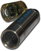
A Remote Ocean Systems CE-X-18 underwater
camera is used to view objects in front of the vehicle. The vehicle also
uses an Inuktun FireEYE underwater camera that faces downwards from the
vehicle. Each camera outputs an NTSC signal with 525 horizontal scan
lines that the Embedded Technologies VFG7330ER frame grabber can convert
to either an MJPEG or MGPEG-4 digital signal. That digital signal is
then used for object detection and recognition by the software on the
vision node.
Object Detection & Recognition
The object detection and recognition software
used in the Stingray’s vision system was developed by the iBotics team
using the OpenCV computer vision libraries. Captured images are
decomposed into hue, saturation, and value (HSV) components so that a
single coordinate represents all color information independent of
lighting fluctuations. The planner sends commands to the vision node,
instructing it as to which objects it should be looking for. A new image
is created for the specific mission task by converting the received
image into a black and white representation where white symbolizes the
color associated with the current task, and black is everything else.
To reduce the unwanted effects of image noise, the images goes through a segmentation process where morphological operations are performed on the image to dilate and erode the image resulting in a single, solid object. After the segmentation process, the binary-valued pixels of the image are added. If the resulting sum is greater than a predetermined threshold, the object is considered present in the scene.
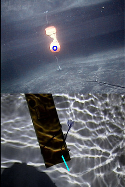
To use the vision data for navigation control, the objects must me localized within the image once they are detected. To determine the relative position of an object, the centroid of the object's area is calculated and reported to the planner. For tasks that require the vehicle to maintain a fixed position relative to the target, the difference between the center of the images and the center of the detected object is used to drive the PID loops.
Determining the orientation of objects, such as pipes, requires additional calculations. To find the orientation of pipes relative to the vessel, a least-squares line estimate is made based on the object’s edges. From this, a relative yaw angle is calculated and sent to the navigation subsystem.
To reduce the unwanted effects of image noise, the images goes through a segmentation process where morphological operations are performed on the image to dilate and erode the image resulting in a single, solid object. After the segmentation process, the binary-valued pixels of the image are added. If the resulting sum is greater than a predetermined threshold, the object is considered present in the scene.
To use the vision data for navigation control, the objects must me localized within the image once they are detected. To determine the relative position of an object, the centroid of the object's area is calculated and reported to the planner. For tasks that require the vehicle to maintain a fixed position relative to the target, the difference between the center of the images and the center of the detected object is used to drive the PID loops.
Determining the orientation of objects, such as pipes, requires additional calculations. To find the orientation of pipes relative to the vessel, a least-squares line estimate is made based on the object’s edges. From this, a relative yaw angle is calculated and sent to the navigation subsystem.
